| Lesson 8 | Reference Architecture |
| Objective | Describe the value and significance of published reference architectures in e-business architecture. |
Value and Significance of a Published Reference Architecture
A published reference architecture is a documented, reusable framework that provides a standardized approach to designing and implementing systems within a specific domain. In e-business, reference architectures serve as the shared vocabulary and structural foundation that allow architects, developers, and business stakeholders to reason about complex systems without rebuilding the conceptual framework from scratch on every engagement.
Their value clusters around three themes: standardization and risk reduction, integration and scalability, and compliance and knowledge sharing.
Standardization and risk reduction. A reference architecture encodes the lessons of prior implementations — the common challenges, the proven patterns, the pitfalls that cost time and money when encountered without preparation. An architect working from a published reference architecture does not navigate these problems from first principles; they inherit a body of accumulated knowledge that significantly reduces implementation risk. This is particularly valuable in e-business, where technology and business models evolve rapidly and the cost of architectural mistakes compounds over time.
Integration and scalability. E-business systems do not operate in isolation. They must communicate with payment processors, ERP systems, supply chain platforms, marketing automation tools, and customer data platforms — each with its own API, data model, and failure modes. A reference architecture that is built with interoperability in mind defines the integration patterns, interface standards, and data exchange protocols that make these connections reliable and maintainable. It also provides a framework for scalability — defining how the system grows without requiring a full rebuild of its foundational structure.
Compliance and knowledge sharing. E-business systems operate under a growing body of regulatory requirements — PCI DSS for payment data, GDPR and CCPA for customer data, accessibility standards for user interfaces. A published reference architecture that incorporates these requirements provides guidance on how to build systems that meet legal and security standards by design rather than by retrofit. When reference architectures are the result of industry collaboration — as the OSI model and TCP/IP model were — they also represent a body of collective knowledge that benefits the entire ecosystem, not just individual organizations.
Why Reference Models Emerged: The End of the Mainframe Era
The need for reference models became apparent in the mid-1980s, when the monolithic, single-tier architecture of the mainframe began to give way to desktop computing and client-server architecture. The mainframe had been a self-contained system — all processing, storage, and presentation occurred within a single controlled environment. When that environment fragmented into networks of heterogeneous machines, the assumption of a single unified system broke down.
It became increasingly apparent that separating technology, information, and business process domains — without a framework for how those domains should interact — was producing dysfunctional systems that could not interoperate. A machine from one vendor could not reliably communicate with a machine from another. Applications built on one platform could not exchange data with applications built on a different platform. The industry needed a common language for describing how systems should communicate, and that need produced the first generation of reference models.
A reference model is a diagram used for understanding — a conceptual framework that people reference to help them make decisions or create an architecture. The OSI model was the most significant of these early reference models, and it remains the primary conceptual framework for inter-computer communications today.
The OSI Seven-Layer Model
The Open Systems Interconnection (OSI) model is a product of the Open Systems Interconnection effort at the International Organization for Standardization (ISO). Development began in 1978, prompted by the lack of interoperability between computers from different manufacturers. The model was formally published in 1984 and established the architectural pattern that all subsequent networking standards have referenced.
The OSI model divides the problem of network communication into seven layers, each of which performs a specific set of functions. A layer provides services to the layer above it and receives services from the layer below it. Two instances at the same layer on different hosts interact as peers — each behaves as though it has a direct connection to its counterpart, regardless of the physical path the data takes between them.
The OSI reference model was produced by an ISO working group. An ISO working group is a small group of experts representing participating countries in an ISO Technical Committee or Sub-Committee. These experts contribute their subject-matter expertise — not their national interests — to resolve terminology, interpretation, and technical details. The outcome is an international standard that reflects collective expert consensus.
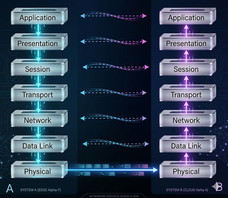
Each layer in the OSI model has a defined scope and a set of protocols that operate within it. It is standard practice to refer to layers by number rather than name — Layer 1 rather than Physical, Layer 4 rather than Transport.
- Application Layer (7): The layer the user interacts with directly. It supports application and end-user processes, identifies communication partners, establishes quality of service parameters, and handles user authentication and data syntax constraints. Everything at this layer is application-specific. Modern Layer 7 examples include REST APIs, gRPC, WebSocket, HTTP/3, and traditional protocols such as HTTP, FTP, SNMP, and SMTP.
- Presentation Layer (6): Provides independence from differences in data representation by translating between application and network formats. Handles encryption, decryption, compression, and data format conversion. Sometimes called the syntax layer. Modern Layer 6 examples include TLS 1.3 for encryption, JSON, XML, and Protobuf for data representation, alongside legacy formats such as ASCII, JPEG, and MPEG.
- Session Layer (5): Establishes, manages, and terminates connections between applications. Coordinates conversations, exchanges, and dialogues between application endpoints. Particularly important in e-commerce, where a transaction must not be disturbed by load-balancing or session interruption during processing. Layer 5 examples include RPC, SQL session management, and NetBIOS.
- Transport Layer (4): Provides transparent transfer of data between end systems and is responsible for end-to-end error recovery and flow control. TCP operates at this layer, providing reliable ordered delivery. UDP provides lower-overhead unreliable delivery for applications that prioritize speed over reliability. QUIC — the transport protocol underlying HTTP/3 — operates at this layer, providing TCP-equivalent reliability with significantly reduced connection establishment latency. The dispersednet.com network security course covers transport layer security in depth, including TCP/UDP behavior under firewall and NAT conditions.
- Network Layer (3): Provides switching and routing, creating logical paths for transmitting data from node to node. IP operates at the network layer, as do routers. Handles addressing, internetworking, error handling, congestion control, and packet sequencing. Modern Layer 3 examples include IPv4, IPv6, and MPLS.
- Data Link Layer (2): Encodes and decodes data packets into bits, handles errors in the physical layer, manages flow control and frame synchronization. Divided into the Media Access Control (MAC) sublayer — which controls how a device gains access to the network medium — and the Logical Link Control (LLC) sublayer, which handles frame synchronization and error checking. Modern Layer 2 technologies include Ethernet (IEEE 802.3), Wi-Fi (IEEE 802.11ax), and 5G NR for wireless access.
- Physical Layer (1): Conveys the bit stream — electrical impulse, light, or radio signal — through the network at the physical and electrical level. Defines cables, connectors, signal characteristics, and network interface hardware. Modern Layer 1 examples include fiber optic cabling (single-mode and multi-mode), copper Ethernet (Cat 6a, Cat 8), and wireless physical interfaces (5G NR, Wi-Fi 6E).
TCP/IP: The Applied Standard
The TCP/IP model is the most widely deployed reference model in practice. It predates the OSI model in commercial deployment and achieved de facto standard status through early adoption by the US Department of Defense — though the DoD did eventually formally adopt the OSI model. TCP/IP maps the OSI seven-layer model to four layers, collapsing the OSI session and presentation layers into the application layer and combining the OSI data link and physical layers into a single network access layer.
The NB2-modernized diagram below shows the TCP/IP model as it applies to modern infrastructure — mapping the four TCP/IP layers to contemporary technologies between an edge node and a cloud instance.
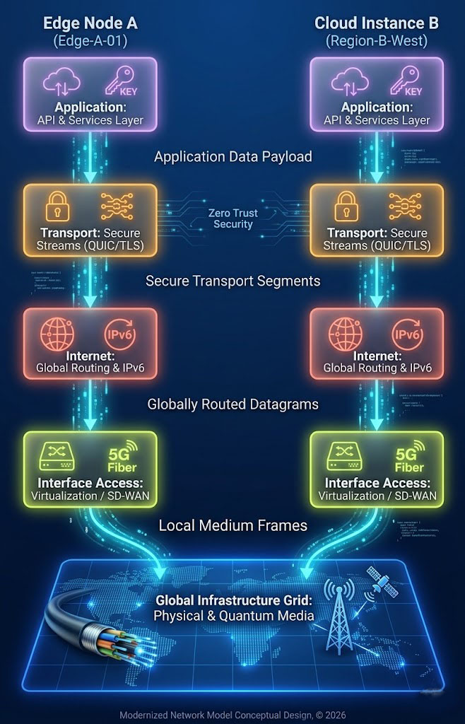
The modern TCP/IP stack reflects thirty years of evolution from the original four-layer model. At the transport layer, QUIC has emerged alongside TCP and UDP as a primary protocol — it provides TCP-equivalent reliability with dramatically lower connection establishment overhead, and it underlies HTTP/3, the current version of the web's primary application protocol. At the network layer, IPv6 has become the standard for new deployments as IPv4 address space exhaustion has accelerated. At the interface access layer, SD-WAN has replaced Frame Relay and ATM as the WAN technology for enterprise branch connectivity, and 5G NR provides the wireless access layer for mobile and edge deployments.
A peer-to-peer basis describes the interaction model between corresponding layers on different hosts. Peer-to-peer interaction is characterized by network-based organizational structures, a shared common resource base, and the assumption that all participants have the potential to make constructive contributions. In networking terms, this means each layer on the sending host communicates conceptually with its counterpart layer on the receiving host, regardless of the physical path the data takes between them.
The Zachman Framework
One of the first reference models specifically designed for enterprise architecture was the Zachman Framework, developed by John Zachman in the 1980s. Zachman organized the architecture space along two axes: perspectives and domains.
The perspectives axis represents the different roles involved in an architecture engagement — from the executive owner who defines the purpose and scope, through the business manager who defines the processes and relationships, to the architect who defines the logical model, to the engineer who defines the physical design, to the subcontractor who defines the detailed implementation. Each perspective has a different relationship to the artifact being designed and a different set of concerns about it.
The domains axis represents the different interrogatives that architecture must answer: What (data), How (function), Where (network), Who (people), When (time), and Why (motivation). Every cell in the resulting matrix represents the artifacts that a specific perspective produces for a specific domain — the architect's logical data model, the engineer's physical network design, and so on.
The Zachman Framework remains actively maintained and in use in 2026. It does not prescribe a process for creating architecture — it is a classification schema for architectural artifacts. Its value is in providing a complete map of the problem space, ensuring that no perspective and no domain is overlooked in an architecture engagement.
With the advent of distributed computing and the development of the services concept, the Zachman Framework evolved, and practitioners began adopting layered models for thinking about IT architecture — the approach that produced the layer cake.
The E-business Architecture Layer Cake
- Technical Infrastructure
- Technical Applications Services
- Application Architecture
- Information Architecture
- Business Architecture
The layer cake model was adopted by most IT professionals as a practical framework for thinking about enterprise architecture, particularly in the context of ERP systems and large-scale application portfolios. It organizes the architecture into five layers stacked from infrastructure at the base to business architecture at the top, with Technology Architecture encompassing the lower layers.
The key insight of the layer cake is the principle of abstraction layers: customize and extend application functionality using abstraction layers rather than in the application package itself. This principle — that modification should occur at the boundaries between layers rather than inside the packages — is the architectural discipline that prevents the platform lock-in described in Lesson 7.
The layer cake had real limitations, however. Viewing the architecture from different stakeholder perspectives required significant "slicing and dicing" — mentally reorienting the framework to show what each stakeholder group needed to see. While it worked well for IT professionals reasoning about ERP systems, it did not convey useful information to business stakeholders unfamiliar with the IT domain. The framework that was designed to enable communication across perspectives often failed to do so in practice.
The BIT Cube: Conceptual, Logical, Physical
- Business Architecture
- Information Architecture
- Technical Applications
- Technical Apps Services
- Technical Infrastructure
The BIT cube extended the layer cake by adding two additional dimensions: scale and view. Architecture artifacts are organized not just by layer but by the scale at which they apply — from Global down through Enterprise, System, Application, Framework, Microarchitecture, to Build — and by the architectural view they represent: Conceptual, Logical, or Physical.
The cube's strength is its comprehensiveness. It provides a location for every architectural artifact, organized by layer, scale, and view simultaneously. Its weakness is the same comprehensiveness: the artifacts it organizes are difficult to integrate as a continuous thread through the business, information, and technology architecture views. Treating business, information, and technology architectures as separate steps — each occupying its own face of the cube — makes it hard to see how decisions in one domain affect the others.
With the emergence of e-business, this separation became a more serious problem. In e-business, the boundaries between technology architecture, information architecture, and business architecture are not clean. A decision about which commerce platform to adopt is simultaneously a technology decision (what APIs are available?), an information decision (how is the product catalog structured?), and a business decision (what business processes does the platform support or constrain?). Treating these as separate architectural steps, to be reconciled after the fact, produces exactly the kind of dysfunctional, non-interoperable outcomes that motivated the creation of reference models in the first place.
The architect's framework must enable the integration of these separate dimensions — automatically reconciling and aligning the requirements of various stakeholders across the natural partitions of the problem space. Creating separate business, information, and technology architectures in sequence no longer works in e-space. The building blocks of architecture module, which follows this one, introduces the approach prescribed by this course for addressing that challenge.